In addition to the expansion in the direction of polarization, which is utilized with longitudinal actuators, a contraction always occurs in the piezo actuator that is orthogonal to its polarization when it is operated with an electric field parallel to the direction of polarization.
This so-called transverse piezoelectric effect is used by contracting actuators, tube actuators, or bending actuators.
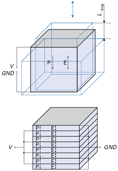
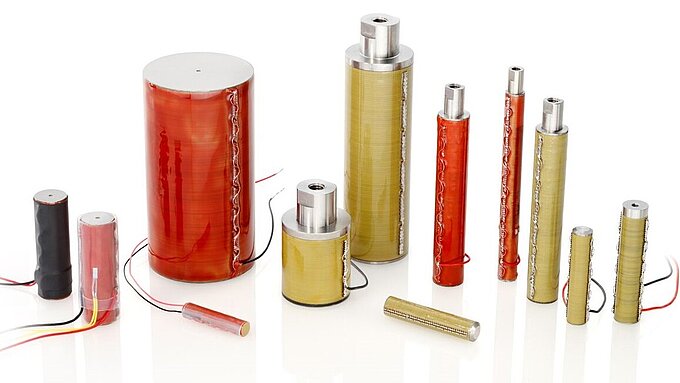
In longitudinal piezo actuators, the electric field in the ceramic layer is applied parallel to the direction of polarization. This induces a strain or displacement in the direction of polarization. Individual layers give relatively small displacements. In order to achieve technically useful displacement values, stack actuators are constructed, where many individual layers are mechanically connected in series and electrically connected in parallel (fig. 1).
Longitudinal stack actuators are highly efficient in converting electrical to mechanical energy. They achieve nominal displacements of around 0.1 to 0.15 % of the actuator length.
The nominal blocking forces are in the order of 30 N/mm2, relative to the cross-sectional area of the actuator. Values of up to several 10,000 newtons can thus be achieved in the actuator.
Longitudinal stack actuators are excellently suited for highly dynamic operation due to their high resonant frequencies. A mechanical preloading of the actuator suppresses dynamically induced tensile forces in brittle ceramic material, allowing response times in the microsecond range and a high mechanical performance.
Estimation of the longitudinal displacement where:
Shear Actuators
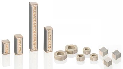
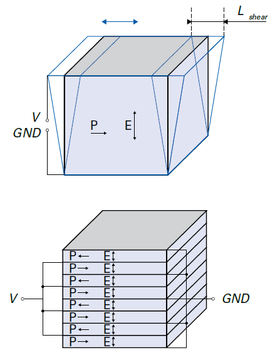
In piezoelectric shear actuators, the electric field in the ceramic layer is applied orthogonally to the direction of polarization and the displacement in the direction of polarization is utilized. The displacements of the individual layers add up in stacked actuators here as well (fig. 2).
The shear deformation coefficients d15 are normally the largest piezoelectric coefficients. When controlled with nominal voltages, the piezo ceramics achieve d15(GS) values of up to 2000 pm/V. The permissible controlling field strength is limited in order to prevent a reversal of the vertically oriented polarization.
When lateral forces act on the actuator, the shear motion is additionally superimposed by a bending. The same effect occurs in dynamic operation near the resonant frequency.
Furthermore, shear stresses cannot be compensated by a mechanical preload. Both limit the practical stacking height of shear stacks. Shear actuators combined with longitudinal actuators yield very compact XYZ stacks with high resonant frequencies.
A typical application for shear actuators are drive elements for stick-slip motors.
Estimation of the displacement of a shear actuator where:
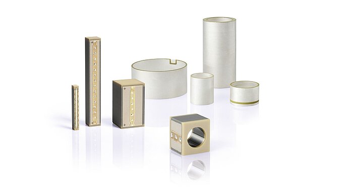
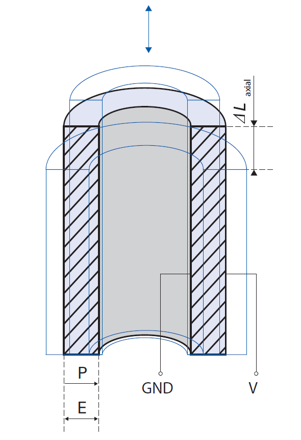
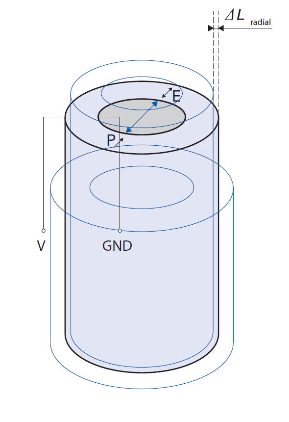
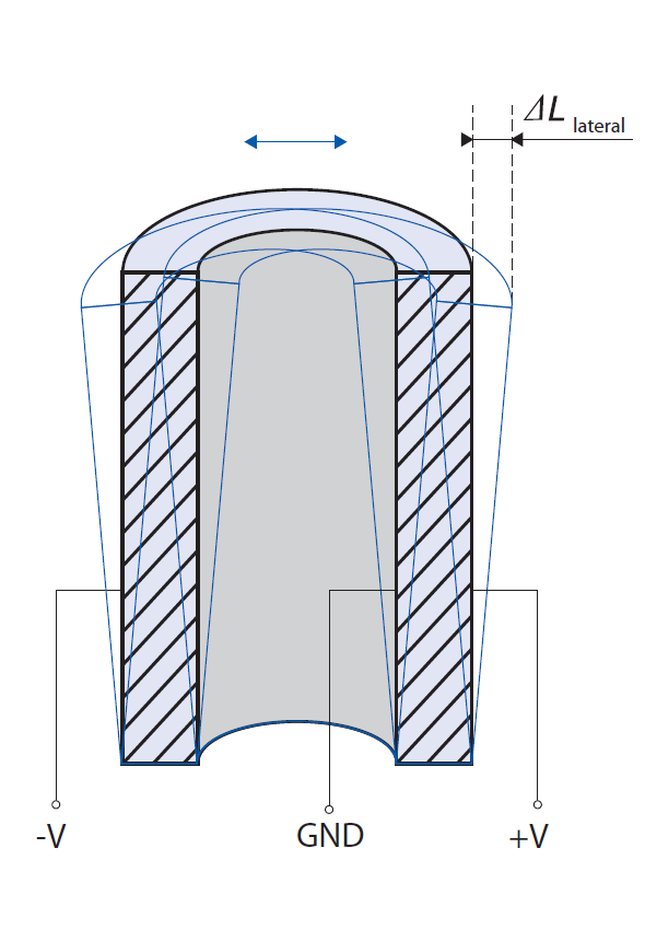
Tube actuators are radially polarized. The electrodes are applied to the outer surfaces, so that the field parallel to the polarization also runs in a radial direction. Tube actuators use the transverse piezoelectric effect to generate displacements. Axial displacements or changes in length (fig. 3), lateral motions such as changes in the radius (fig. 4), as well as bending (fig. 5) are possible.
In order to cause a tube to bend, the outer electrode is segmented into several sections. When the respectively opposite electrodes are driven, the tube bends in a lateral direction.
Undesirable tilting or axial motions that occur during this process can be prevented by more complex electrode arrangements. For example, an eight-electrode arrangement creates a counter bending and overall achieves a lateral displacement without tilting.
Tube actuators are often used in scanning probe microscopes to provide dynamic scanning motions in open-loop operation, and as fiber stretchers. Further application examples are microdosing in the construction of nanoliter pumps or in inkjet printers.
For all tube dimensions, see data sheet >> PT120 – PT140.
| ΔLaxial | Axial tube displacement [m] |
| ΔLradial | Radial tube displacement [m] |
| ΔLlateral | Lateral tube displacement [m] |
| d31(GS) | Transverse piezoelectric large-signal deformation coefficient [m/V] |
| l | Tube length [m] |
| ID | Internal tube diameter [m] |
| t | Tube wall thickness (=(OD-ID)/2) [m] |
| V | Operating voltage [V] |
| GND | Ground |
| P | Direction of polarization |
| E | Electric field strength |
Contracting Actuators
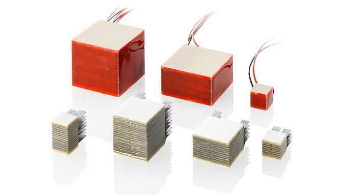
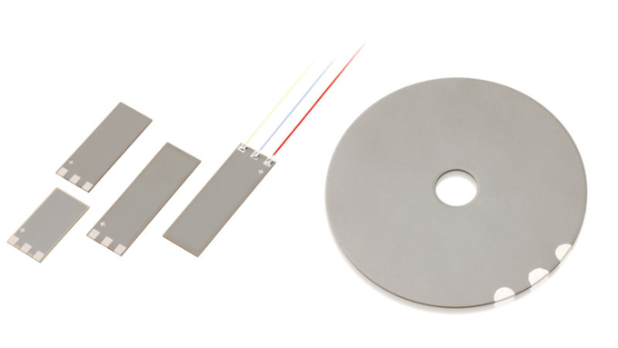
Typically, piezo contractors are flat components. Their displacement occurs perpendicularly to the polarization direction and to the electric field. The displacement of contracting actuators is based on the transverse piezoelectric effect whereby up to approx. 20 µm is nominally achieved.
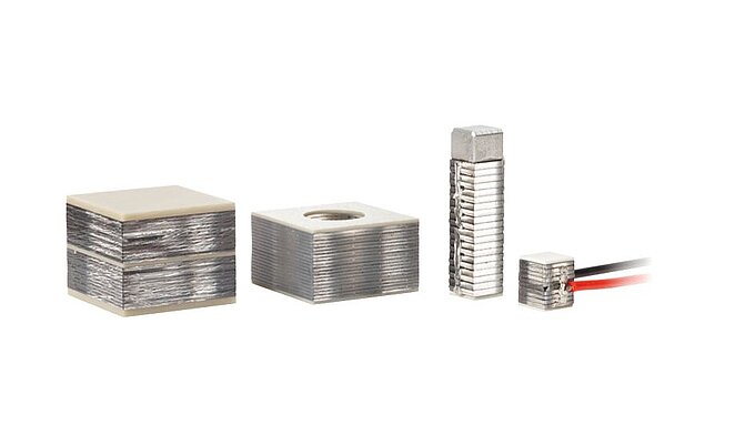
Multilayer elements offer decisive advantages over single-layer piezo elements regarding their technical realization: Due to the larger cross-sectional area, they generate higher forces and can be operated at a lower voltage (Fig. 6).
As a result of the contraction, tensile stresses occur that can cause damage to the brittle piezo ceramic. A preload is therefore recommended.
Estimation of the transverse displacement of a contracting actuator where:
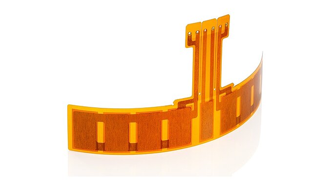
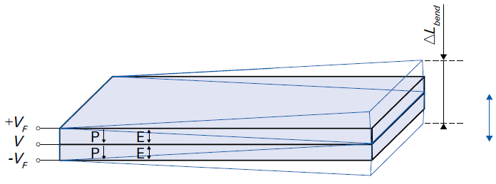
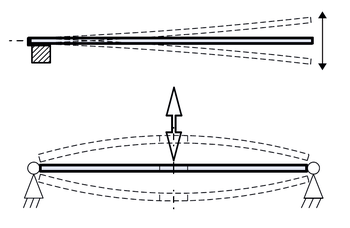
Attached to a substrate, contracting actuators act as bending actuators (fig. 7). For the construction of all-ceramic benders, two active piezoceramic elements are joined and electrically driven. If a passive substrate made of metal or ceramic material, for example, is used, the substrate is referred to as composite bender. The piezoceramic elements can be designed as individual layers or as multilayer elements. Piezoelectric bending actuators function according to the principle of thermostatic bimetals. When a flat piezo contracting actuator is coupled to a substrate, the driving and contraction of the ceramic creates a bending moment, which converts the small transverse change in length into a large bending displacement vertical to the contraction. Depending on the geometry, translation factors of 30 to 40 are attainable, although at the cost of the conversion efficiency and the force generation. With piezoelectric bending actuators, displacements of up to several millimeters can be achieved with response times in the millisecond range. The blocking forces, however, are relatively low. They are typically in the range of millinewtons to a few newtons.
| ΔLbend | Bending displacement [m] |
| d31(GS) | Transverse piezoelectric large-signal deformation coefficient [m/V] |
| n | Number of stacked ceramic layers |
| V | Operating voltage [V] |
| lf | Free bender length [m] |
| hp | Height of the piezoceramic element [m] |
| Rh | Ratio of substrat height (hs) and piezoceramic element height (hp) in a composite bender (Rh=hs/hp) |
| RE | Ratio of the moduli of elasticity of substrate (Es) and piezoceramic element (Ep) in a composite bender (RE=Es/Ep) |
| VF | The fixed voltage for bender control [V] (V and VF can be superimposed by an offset voltage) |
| GND | Ground |
| P | Direction of polarization |
| E | Electric field strength |







![Bending Displacement [m] (parallel circuiting) Bending Displacement [m] (parallel circuiting)](/fileadmin/user_upload/pi_ceramic/IMG/PIC_Gleichung_7.png)

![Bending Displacement [m] (Two-Layer Composite Bender) Bending Displacement [m] (Two-Layer Composite Bender)](/fileadmin/user_upload/pi_ceramic/IMG/PIC_Gleichung_9.png)

![Bending Displacement [m] (serial circuiting) Bending Displacement [m] (serial circuiting)](/fileadmin/user_upload/pi_ceramic/IMG/PIC_Gleichung_8.png)

![Bending Displacement [m] (Three-Layer Composite Bender) Bending Displacement [m] (Three-Layer Composite Bender)](/fileadmin/user_upload/pi_ceramic/IMG/PIC_Gleichung_10.png)


